

Short descripition:
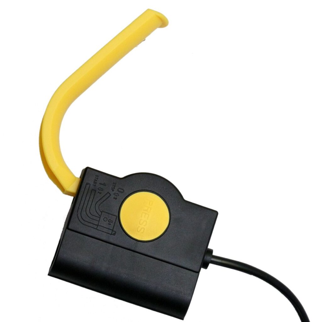
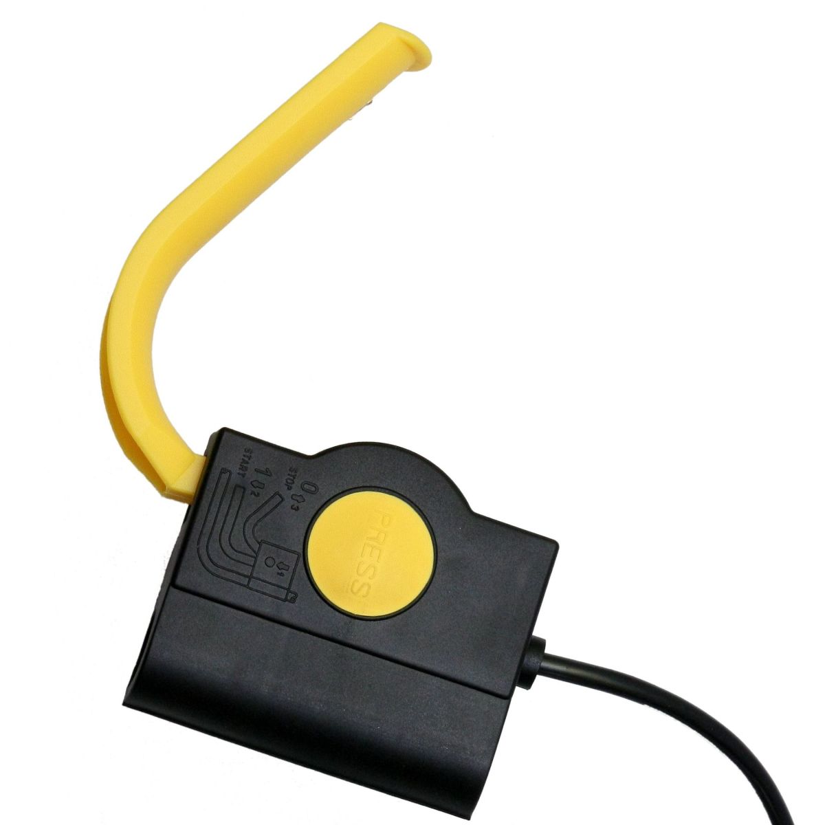
KD… type switches enable safe ON-OFF switching and operation of electric gardening machines (primarily lawn mowers).
KD fűnyírókapcsoló
Installation:
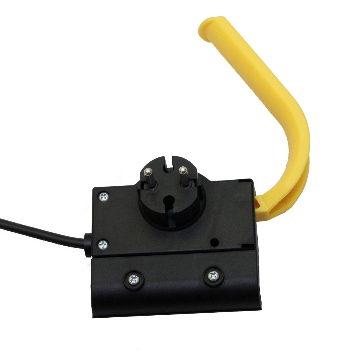
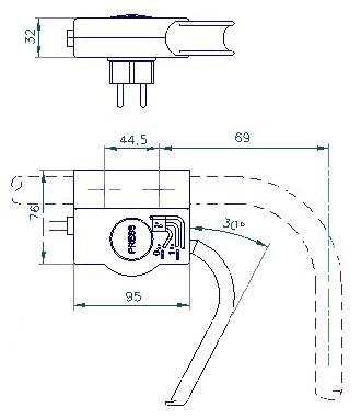
The switch is fixed to the right side of the upper handle of the machine. The handle tube size can be 20-22 mm. The inclination angle of the handle tube connecting to the equipment can be 5-75o horizontal. The orientation pins of the switch must be fitted to the positioning holes of the handle tube, then the clamp on the switch must be screwed onto the handle tube and secured with 2pcs of 3x30mm D-head screws (included). After installation, the diagram on the cover of the switch box, illustrating the operation, must be readable from above. The distance between the positioning holes on the handle tube is 44.5 mm. The distance between the center line of the first hole and the center line of the handle part of the tube is 96mm.
After pressing the membrane labeled “PRESS” on the switch and pulling the operating lever toward the handle the switch turns on. Releasing the lever turns the switch off again. Without pressing the membrane, the switch cannot be turned on by pulling the operating lever.
Technical details:
Design | The switch box is rewireable, and can be used with H05VV-F type 2×0.75-1.5mm2 connection wires. |
Applied standard: | EN61058-2-1 |
Force required to operate the switch: | ~13N |
Design of the switch connection terminals (in case of replacing the cable included): | 4 screwless, spring-loaded connection terminals, to which insulated flexible wires with a cross-section of 0.75-1.5mm2 and a ferrule are connected. The connection can be made by inserting the wires into the openings on the side of the switch to a depth of at least 8mm. After connecting, the spring connection becomes self-closing. The connections can be released by breaking through the reliefs on the bottom cover of the switch, through the openings created in this way, and by lifting the clamping springs with a tool (e.g.: a screwdriver with a blade width of max. 3mm). The connection terminals are suitable for connecting 2-2 wires. The connections can be made before installing the switch in the device, and the disconnection can be done after removing it from there. |
Electrical load capacity and service life according to EN61058-1: | 8(8)A; 250V~; 5E4 switching cycles |
Combustibility level of the plastic parts of the switch: | For plastic parts in contact with current-carrying parts, min. V2 (according to UL94) |
Creep current strength of the plastics used in the switch: | min. PTI250 |
Creep paths and clearances: | min. 3mm |
Pollution type: | normal |
Utilization category: | C (IEC 335–1) |
Applied standard: | EN61058-1 |